“Snappy”…A Band Switching Portable Dipole by Clair Cessna, K6LG
Since I enjoy outdoor operating activities, QRP events, Field Day, and others, I needed an antenna which could be thrown in a backpack, quickly deployed, and easily used on several HF bands. A segmented dipole was put together, using bullet connector “switches” across insulators to change bands… reducing the necessity of using an antenna tuner.
The antenna is usually configured as an inverted Vee supported in the center at about 16 feet, using a SD-20, 20 foot, telescoping, fishing pole. Alternatively, it can be suspended from a tree branch. The ends are usually near ground level or supported by bushes, trees, rocks, etc.
“Band switching” for the five bands is simply a matter of shorting across selected insulators to adjust the antenna, using the bullet connector shorters (switches.) Since the antenna is usually relatively close to the ground, or can be easily lowered from the ends to clothesline height, one can rapidly walk along, and change the antenna length.
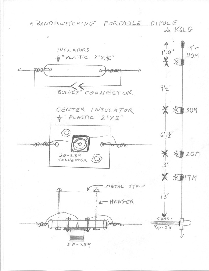
Materials needed for construction: Forty feet of #16 or #22 plastic jacketed speaker wire (Lowes or Home Depot); small sheet of one-eighth inch thick Lucite or other plastic for insulators, ten bullet or spade connectors (Radio Shack), piece of quarter inch thick plastic, two inches square, SO-239 connector.
Cut to the lengths shown below, but add 3 inches to each for connecting through the insulators. Since you will be unzipping the speaker wire later, both sides of the antenna will be the same for each segment. Strip an inch and a half off the ends of each segment and insert the insulators. Solder short leads to the male and female parts of the bullet connectors and solder in place across each insulator, leaving enough slack so they can be easily plugged in or unplugged. (I prefer the bullet connectors since they are easier for my fingers to manipulate.)
Measurements beginning from the center (middle of insulator to middle of next 2” insulator) should be 12‘ 7“, 3‘ 6“, 6‘ 0“, 9‘ 1“, 1‘ 7“. (Remember to add 3″ to each of these lengths for attaching to insulators and bullet connectors.) These measurements are for 17, 20, 30, 40/15M, and cut for the low end of these bands. Notice that for 15M the entire antenna length is used. The 1′ 6” end section is used on 40/15M to facilitate matches on those bands depending on whether the end of the dipole is staked to the ground or elevated in a tree. The antenna is fed with RG-58 coax. No balun is used.
Generally these measurements provide a satisfactory match. Of course in the field, antenna height, configuration, and environment may sometimes be different, so, when possible, I carry an MFJ Tiny Travel Tuner to deal with any variations.
The “Snappy” is a snap to build, and to set up in the field. For band changes, just snap or unsnap the connectors!
de Clair Cessna K6LG 8-22-2011